Thursday, 10 October 2019

IVA Application - A murky path oft trodden!

I have managed (with the help of AK!) to get to the momentous stage of applying for the IVA test.

For most people that undertake the building of a machine as complex as a car that is legal to drive on the road, it would seem that the IVA application is the most confusing part of it all.

In my opinion, this is not made any easier by the "non-English" English that DVSA use in many of their forms and guidance documents!

So, I thought it might be useful to document my experience to help the many people that will follow me on this path.

Before I document my experience, I also found Ant's blog very useful and he also has a page on the actual application forms which is very useful and details the forms that need to be completed.

Ant's Cobra IVA Page 

(be aware that there are thumbnails of the "IVA 1C" form, and it looks like page 3 is duplicated, but if you click on the 2nd thumbnail it actually opens a picture of the 2nd page)

I will not duplicate that effort here, so you can read this for yourselves and I will try and fill in my experience of the process.


Here is the list of files that I submitted:


This includes the following:

  • IVA 1C form - main application form
  • IVA 4 Amateur Built Declaration form
  • 17 pictures taken throughout the build - this blog helped a lot!
  • 8 receipts for items bought throughout the build - most importantly
    • The receipt for the chassis/kit from the manufacturer showing the VIN
    • Gearbox receipt
    • power steering rack receipt
  • V5 for the donor vehicle
    • I did not have a receipt for this, and did not submit one and this was not an issue
  • Engine Age Certificate
You will note that all of the files except the DVSA forms are "JPG" files as I did not have scans of them and could only use photos taken from a smart phone - this did not seem to be an issue for DVSA and did not cause any delay to the application.
I also names all the files with the VIN number to try and help keep all the documents together.

I submitted the application online using DVSA's TAS system: www.gov.uk/dvsa

There is a single upload field for the IVA 1C form, and then all other files are uploaded to the second upload area - you have to upload one file at a time, but I had not issue uploading them all. I know some builders have said they could not upload everything (not sure why), but once you have you application reference number you can simply email DVSA with any additional documents using that reference number.

Once you have uploaded and submitted the documents, you will receive an automated email from the TAS system stating the following:

Thank you for your Technical Test Application 1/AKG2CPBxxxxxxxxxx.Your reference number for this application is TAS 3xxxxx. If you wish to provide any further information in support of your application then please use your email software's 'Reply' function and leave the subject line unchanged.

This did not come through immediately so I assume is based on some automated system timing.

After 5 days, I got another email from the TAS system with the subject "[TAS 3xxxxx] - Application Assessed".

The content of this email was as follows:

Dear Applicant
Your application for Individual Vehicle Approval is now ready for payment.

NOTE: If you have not already done so, you can make payment for your application and book your test appointment, where appropriate.
Vehicle Identification Number:  AKG2CPBxxxxxxxxxx
If paying by Pre-Funded account, the test fee will be debited accordingly and the transaction will be shown on your monthly statement.
If paying by Credit/Debit Card, please contact us as soon as possible on 0300 123 9000 and select Option 1(from 07:30 to 18:00, Monday to Friday), with your TAS ID number to make a payment. If you have nominated a DVSA testing facility for your IVA, MSVA, or Coif Scheme application you will also be able to book a test appointment.
Please Note: [1] If you have submitted an HGV or Trailer Technical Application which requires an inspection you will be contacted shortly.
[2] If payment is NOT received within one month this may result in your application being cancelled.
NOTE:*** Changing Vehicle Approval test appointments ***From 1 July 2019, we will be changing the way you can change test appointments you have made.You can only change the appointment twice, and you must do it before midday on the working day before the appointment.You won't be able to change it a third time.In addition, you can get a different vehicle tested at an appointed time, provided:• both vehicles already have an appointment booked• the appointment is booked using the same prefunded account, or by the same applicant if paying by card• the vehicle is the same test category with the same test durationIf you don't bring the vehicle to the third appointment you make, the relevant cancellation policy will apply.Any test appointment changes DVSA has to make due to unforeseen circumstances will not be counted as part of your test allocation.
Yours faithfully
Customer Service Centre TeamDriver and Vehicle Standards Agency | The Ellipse Building, Padley Road, Swansea, SA1 8AN

I excitedly phoned up almost straight away (which is odd as the next part makes you £450 poorer!) and paid my money - I did not book a test date at this point as AK are presenting the car for the test so they will arrange this directly.

I was told on the phone that I would receive an email receipt and that was the application complete.

This made the next email received a bit confusing, which was another reason I wanted to write this.

The next email was from "VOSA_ADMIN", it was received about 1.5 days after calling up to pay and the subject was "Your recent application for Booking Ref:1-xxxxxxxxxx":

Dear MARK HARNETT,
Thank you for your recent application for a IVA BAS M1 CAT.A,C,S TEST for your vehicle/trailer. Due to the nature of your booking this has been referred to the DVSA Testing and Support Services (TaSS) in Swansea. You will receive email confirmation once your application has been processed.
Terms & ConditionsPlease visit our website at https://www.transportoffice.gov.uk/crt/doitonline/bl/help/etbtermsandconditions.htm for more details.
Thank you,
DVSA

As stated, I was confused by this - they make it sound like there is something out of the ordinary with the application and it has been referred to Swansea. By this time the office had closed so I could not call up to query it, so I decided to do that first thing in the morning - I had also not received an emailed receipt.

When I woke in the morning, I had the emailed receipt, so was a little more at ease, but decided to call up anyway.

The answer was that this was all normal, and the referral is just the application being released to the next stage and it was ready for the test to be booked.

This is as far as I have got and now waiting for AK to book the test! I hope this has been useful to someone.


Monday, 23 September 2019

OMG - Where has the time gone?!

Well, after my last post and the clear determination to get the car done, I am happy to say that it is almost done.

I am less happy to say that we were just not able to finish it ourselves.

Life seems to have a habit of getting in the way, and as I moved house and my Dad has been pretty busy, we have just not had the ability to get it done.

So, the decision was made that it would go to AK to be finished off.

We managed to get it to rolling chassis stage, so AK are completing it from there.

I did get this one update picture after she just came back from the paintshop:


The colours are Aston Martin Tungsten Silver with Wimbledon White stripes - I am not sure of the official name for the red detail stripe!

The interior will be anthracite with red stitching.

I will post some more pictures when she is finished.

I really hope this blog has helped some people up to the points I have managed to document.

Wednesday, 20 June 2018

Looks like it has been another two years!

Well, seems like time has flown by again without much progress on the car.

Started back on it again now and determined to get it done this time.

The body shell has now been taken off while we tinker with some final parts before fitting the shell permanently.

We were not happy with the handbrake mechanism, so have made some modifications to that.

We also decided to get the engine running and ensure there are no leaks and it runs ok before fitting the shell. This was a wise decision as there were some minor oil leaks from the rocker covers not sealing properly and also number 3 cyclised was running much hotter than the rest - the exhaust header turned a nice cherry colour! We ended up checking the valve lash and 3 was extremely loose, so after adjustment we are hoping that fixes it.

All the radiator connections are in and no leaks in that, so happy there.

Will hopefully be doing some more regular updates now.


Friday, 26 August 2016

Dashboard layout

This seems to be an area where personal taste really dictates the outcome of the dashboard layout. I deliberated over this for some time, and finally settled on a layout that I am happy with.

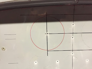
For a long time I pondered the task of transferring the layout on to the dashboard so I could cut it out. The first step of this was to find the centre line, but after that I was not too sure!

I started by measuring the available space where the dials go:


This then allowed me to create a drawing (using Pages on my Macbook, no less!) of how I wanted to the dials to sit together. Using Pages was actually a really good way of doing this, as I could size all of the shapes really easily, and when I dragged them around, useful little alignment lines would pop up so I could get everything aligned just perfectly. 


This is the end result! I printed it out on A3 paper, and the circles are all the exact size of my dials, plus an extra 1mm for when the dash is trimmed.
What I really wanted to go for here was the symmetry given by the top 3 smaller dials mimicking the curve of the body lip. I have also dotted some warning lights around the dials (Battery/charge light above the Volt meter, Oil light above the Oil pressure meter and the hazard and brake test light between the two large dials.


The next part of the puzzle was to transfer the information from this paper to the actually dashboard. I did this by drilling through all the hole centres, as you can here


Once I removed the paper template, you can see that all of the holes line up nicely with my original centre line measurements


I originally bought myself a mathematics compass for drawing circles, but quickly found that the hole to clamp the pen was too small for my permanent markers, so I had to come up with another plan.
I Googled for advice on how to draw circles to specific sizes, and came across a video on how to make a DIY beam compass. So that is exactly what I did. I found a suitable piece of wood (it only had to be quite small) and stuck a screw in one side to act as the pivot and drilled a hole through the other end at exactly 27mm and 50mm (the hole diameters for the Speedhut gauges I have are 54mm and 100mm - with the extra 1mm all round (2mm total) for the dash trim).
I must say that this worked extremely well and I quickly drew all of the circles I needed.


First circle done


Closely followed by all of the others.

This then gave me the outer limits that I need to open the holes up to.


I used a 51mm (2 inch) hole saw for the smaller dials and a 89mm (3.5 inch) hole saw for the larger dials. The warning lights will just be a 14mm hole which I have a 14mm drill bit for.

With the hole saw, I didn't want to cut too close to the edge, so I would have to fine tune by hand. I say by hand, but what this really means is by Dremel!


The Dremel made short work of taking out the remaining fibreglass and I managed to get the holes opened up really easily.

I had to take care not to take too much out as it does disappear quite quickly in to a fine white powder that gets everywhere!

A dust mask is definitely required for this job.


Overall I am really happy with the result.

The next task is to trial fit the dials and drill the holes for the warning lights and toggle switches.

Thursday, 25 August 2016

Steering column - Upper section

I needed to fit the steering column in order to ascertain what size hole I needed to cut out for the dashboard. I wanted to do this before I cut the holes for the gauges in the dashboard to make sure that I got the gauges in a sensible place and they would not be obscured by the steering wheel.


The first task was to cut back the metal shroud that sits on the upper side of the column. I mounted the column roughly in place (you can't get it in properly because the part you need to remove is in the way!)
I marked a line where it hit the scuttle hoop and then took the angle grinder to it......


Before......


This is what it looked like after surgery.....


I had to tweak the brackets slightly as the column did not appear to be sitting quite straight, but only a very tiny amount.


And that's it.....column mounted for now.

I have bought two lengths of 8mm threaded bar so that I can use the trick of being able to easily move the column up and down once the dash is in place without having to hold it. I only needed 2 x 20cm lengths as this was enough to drop the column out of the way of the dash.

Door cards


This is another job that I was trying to get done so that I could take them, along with the dashboard, to AK to be trimmed.

I am a little apprehensive about this job, because it seems to all be a little bit of guess work to make sure the door cards are the right size once trimmed and all the door seals on, as I have no idea what the final thickness will be!

However, all I can do is go with what seems to be right, and if it needs fixing later I will deal with it then.


I decided that I would make some templates out of cardboard, so I offered up a piece (I found out that it needs to be at least 70cm long as the first one I cut was not!).....


....and drew around the door edge on the rear of the cardboard with a red maker pen.


This left me with a nice line to cut along to get the initial template.


I did this both sides and cut out the templates. I was not too worried about them being slightly larger than needed. In fact, this was the preferred option as it was hard to get a clean line with the cardboard, but I knew that I got trim the plywood down to suit once that was the rough size needed.


I then transferred the shape to the plywood......


 ....and cut the plywood out with a jigsaw. Remember to label them up with  side they belong to!


 I then stuck the plywood cutouts back to the door and drew around the back again with the red pen. I stuck the top of the plywood to the door with some gaffer tape to stop it from moving.


This then left me with a line to work to to get a better fit with the plywood. I used the jigsaw again to get closer to the red line, and then filed it down by hand from that point.


This left me with a nice looking pair of door cards that have a nice smooth edge to them.


Thursday, 11 August 2016

Fuel fillers

Another task that I could tackle without having the body fully bolted down was to mount the fuel fillers.


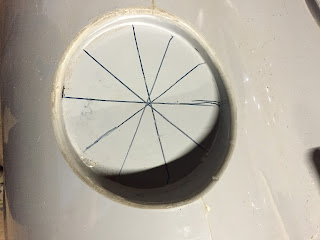
I started by using a trick that I had seen on the Cobra Club forum, of using a straight edge to draw lines across the recess to find the centre


The lines do not match exactly, but I was expecting that because the recess is not perfectly circular


However, when I then put the fuel filler flange directly over the centre, it did not look right, so I decided this was another job like finding the centreline, and did it by eye!


I centred the filler flange and drew around the base. I then drilled a hole directly through the centre.


Using a 72mm hole saw, I then cut the hole out (I was a bit nervous about this!)


But, I was very happy with the result!


I then repeated for the other side (not sure why I decided on the expensive option of having two fuel fillers!).

Even if I say so myself, it looks pretty good.


The next job here is to drill the holes in the filler flange neck and drill the holes in the body to suit. I have purchased some nice stainless steel, raised head, countersunk, slotted screws for this!