Saturday 16 August 2014

Brake and clutch line testing continued

We finally got round to testing the brake lines for leaks. We felt this was best done before the body was fitted so we had good access to fix any problems. 

We are aware, however, that we will have to drain the system down to fit the body, but we now have peace of mind that it is all ok. 

There were a few weeps here and there, but nothing a little tweak up of the joint didn't fix. I'm quite impressed with the Sykes Picavant hand held flaring tool I bought. It did a great job considering this was my first time doing brake flares. 

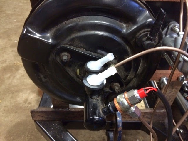
We fitted the reservoir up high to aid the bleeding process. 


The only real issue we had was with the clutch slave cylinder. The surface on the rear of the cylinder does not seem big enough to get a good seal with a copper washer. I bought a new fitting from CBS that will hopefully sort this out as it is more like a flared copper fitting that should seal better. 

Radiator/Cooling system

I had originally intended to do something slightly different to the standard AK setup with the cooling system, but in the end we were making more of a headache for ourselves than we needed to. Therefore, we reverted to the standard AK setup. 

This is all pretty simple to fit. 

I did stick some robber strips along the bottom bracket and under the top bracket to avoid any metal on metal rubbing. Once the radiator is located it is pretty solid. 


Sunday 27 July 2014

Brake and clutch line testing

We decided it was prudent to test all of the brake and clutch lines before we installed the body. This would make it much easier to spot any leaks and nip the unions up accordingly.

We made up a small frame to mount the pedal box roughly where it would be inside the footwell


We the connected up the copper lines, making sure to leave enough to redo this once installed properly. It should be a much neater installation when done properly


I am using a brake light switch that is part of a banjo bolt. I am hoping this will be a better solution than some of the other hydraulic ones that can weep if they are not upright. 

The clevis for the clutch cylinder was interesting. The first one I bought was too short, but I really struggled to find a longer one with a 5/16 female thread. Eventually found one on eBay that has the part number OBPCB005. This is long enough, but does cause the clutch pedal to stick out more than the brake pedal. Something to try and remedy at a later date.......


Power steering

For the power steering, we are using a rack from a BMW E46, and the pump from the same. We needed to get a V belt pulley, which we sourced from Brammer. A bit of machining was needed on the boss in order to drill the bolt holes through.


We made up a bracket to hand the pump off of the water pump. Looks a bit DIY at the moment, but I still need to tidy it up a bit around the edges. It is made out of aluminium, so with a bit of elbow grease should polish to a nice shine.


Saturday 26 July 2014

Painting the engine bay

At a bit of a loose end as really needed an extra pair of hands to test the brake and clutch lines, and my Dad (being a farmer) was out making hay while the sun was shining!

So, I decided it was a good idea to paint the inside of the wheel arches and engine bay. 

I used POR 15 gloss black, and I can now confirm that once it is on you it doesn't come off that easily!

However, I did manage to get more on the car than on myself!

Before


After


Not too much different, but should stop ugly reflections once the wrap comes off the stainless engine bay cladding.


Thursday 24 July 2014

Engine test fit


We decided that it was prudent to test fit the engine to ensure that we had the appropriate clearance for brake lines, clutch line, fuel lines, fuel pump etc.

It was not too difficult to drop it in with the two of us and an engine crane. We made up some brackets to bolt on to the exhaust manifold bolt holes and managed to position them so that the engine and gearbox was relatively balanced. It was slightly heavier on the gearbox end, but that made it easier to get it under the tunnel frame at the back.


This then allowed us to measure up for the propshaft. Fairly straightforward job and the part was ordered from Bailey Morris. They give an excellent service and it was a very quick turnaround.


Bailey Morris have a nice PDF file that you can download and complete with all of the measurements they need. For information, here is the one I completed


The useful information here is the slip yoke (gearbox sleeve) part number!

The other job while testing fitting was to follow a similar process that we did for he fuel tank mounting for the gearbox mount.

We drilled 2 holes down, and welded some M10 threaded bar in place to hold the gearbox.


Bit of a dark picture, and the reflections don't help, but you can just about see the stud coming down with a nut on the end.


Fuel tank


On investigation there was a couple of ways to mount the fuel tank.

We opted to drill through both sides of the box section and weld some 10mm threaded bar in place. You will also notice a black strap that is in the centre of the tank. This is our "belts and braces" approach to add a bit more piece of mind.

The tabs that hold the fuel tank on are just welded at 90 degrees to the side of the tank. I have every confidence that these will never give way, but if for any reason they do, the tank will just fall straight out of the bottom!

The strap is a seat belt from the XJ40 donor, so is very low profile but strong, so should just add that extra security (just in case!). 


Engine fettling...

Just a couple of pics of fitting the flywheel, clutch, pressure plate and starter


Wednesday 23 July 2014

Brake master cylinder remote reservoir

We did not like the position of the reservoir for the brake master cylinder. On the Rover 25 master cylinder it just pushes in to the top. 

It proved quite difficult to source some push fit elbows to make it work with a remote reservoir


I thought I found some Jaguar ones that would fit, but it turned out they were too short. 

After a bit more searching, I finally found ones that fit perfectly. 

It is a plastic elbow from a 1972 VW Beetle. I Got two of them from a site called Megabug, along with the replacement seals. The elbow didn't have a size on the listing on the website, but clearly says it is for a 1972 Beetle. The bottom plug part actually measures 13mm and the hosetail is 8mm. 


The seal is the 12mm/22mm (internal/external diameter) one. It is a little shorter than the Rover one I took off, but it has a little bead that sits in a recess inside the inlet of the master cylinder 
and these are in exactly the same position on both. 

I bought two two seals, but only one needed as the seal closest to the servo is a different type as it has a pipe that goes directly in to the servo itself. 

Now I have these parts, we can crack on with testing the lines for any leaks. 


Saturday 19 July 2014

Full engine fit

With he engine and gearbox together properly, and the clutch arm issue sorted, it was time to drop the setup in (hopefully for the last time!). This was, again, relatively easy with the engine crane and a spare pair of hands to help guide it in. There were a few more obstacles is time though, as the brake, clutch and fuel lines were now in place, so we had to be careful of these. 


Clutch slave

The clutch slave caused us a bit of an issue. At first, the clutch fork was sat right back against the opening in the side of the bell housing. This just did not seem right. I have also read a lot about these slave cylinders and the fact the pushrod seems to be at a funny angle. 

This setup is all from Roadcraft, and I have been led to believe that early versions of these had problems with the pushrod binding, but this has been sorted out in these later versions. 

So, on investigation, the source of our issue seemed to be that the ball that holds the other end of the clutch fork inside the bell housing was the wrong length. Brian at Roadcraft kindly sent us an adjustable one that gives the result below


We screwed the new one in about 8mm further than the old one, and that had the effect of reducing the angle the arm was sat at so it no longer sits against the back of the bell housing. 

The slave cylinder does need to throw the arm quite a way forward to disengage the clutch, however, this is another one of he reasons we are testing the clutch and brake lines before the body is off. 

Clutch line

The clutch line follows a very similar path to the front brake line. We have secured the line roughly every 200mm to ensure we are always well within the IVA requirement of maximum 300mm between fixing points. 


At the end of the pipe we welded a small tab that holds the joiner


Here it is finished and connected to the flexi pipe that goes to the slave cylinder


Fuel line

When looking at the fuel line, we had to decide where the line should go - over or under the diff....

Going over meant a very sharp uphill straight from the tank. Although I am sure the pump would have pulled the fuel through ok, we thought it was much neater to have a straight run going under the diff.

This meant we had to come up with some way of protecting the line if the rear end ever got grounded. 

We are using 10mm micro bore pipe (sources from Wickes!) and managed to find some steel tube that was the right diameter for it to fit through. However, we didn't want the copper pipe rubbing on the steel pipe, so the steel pipe is actually large enough to take the copper pipe with a rubber pipe covering it. You can see this in the 3rd picture below as it exits the pipe. 

This was the initial pipe with a tab welded on to bolt it to the underside of the diff


Here you can see it bolted in place to the diff bracket


And here it is exiting the pipe and then clipped to the chassis. Again, we tried to clip at roughly 200mm intervals as with the clutch and brake lines. You can just about see that the tube is also now painted black to match the rest of the chassis


It is quite a short run of copper, as it then plumbs straight in to the filter which goes immediately in to the pump


All in all very happy with this approach as I am extremely confident the fuel line will be protected from underneath. 


Friday 20 June 2014

The engine lives.....

Only for a brief amount of time, as no coolant system hooked up etc, but we just want to make sure the rebuilt engine we bought fired before we fitted it


An exciting moment to get to, but just need to crack on now so we can get it installed!

Saturday 7 June 2014

Engine time

We are almost at that time where a test fit of the engine is on the cards. This will be in order to make sure the brake pipes etc are all out of the way and also to allow a measurement to be taken to get the prop shaft ordered. 

This got us to thinking that it would be good to test start the engine to ensure there are no problems before the final install. 

I need to get a few bits sorted for this, one of them being the starter motor. On investigation, it appears that my engine has a staggered bolt pattern, so I can't get one of the mini high torque starters. It also means that the 153 tooth flywheel hat came with my gearbox package can't be used. 

Luckily for me, Brian at Roadcraft has agreed to swap the flywheel and clutch for the ones that will work with the staggered starter. That is, I need a 168 tooth flywheel and 11" clutch. 

Once we get all that sorted and the new bits have arrived, we can set to and see if she starts!

It did get me to thinking more about the engine age. Looking at the numbers stamped in the block, it seems that this engine was originally from a 1974 Camaro. 

Once the engine is in, I will get the age verification certificate sorted, and as long as my initial investigations are correct, the good news is that this should mean that the IVA emissions test should only consist of a visual smoke check (as long as I have interpreted the diagram in the IVA manual!)


Rear end done

It had taken a bit longer than I would have liked to get to this stage, but with the a house move and a new job to contend with, there hasn't been much time recently. 

However, I am glad to report that the rear end finally seems to be done!

There were a few teething problems along the way, but got there in the end. 

The suspension arms went on without any problem, and the shocks and springs all lined up without drama. The first problem that I encountered was when trying to fit the caliper carriers to the hub carriers. As you can see from the photo below, I could not get it to line up properly. 

I pondered this for about a week, trying to figure out what the issue could be. The XJ40 I have used as a donor had the older Girling calipers, but I wanted to upgrade to the ATE calipers, so I wondered if this could be causing an issue? However, I was told by a jag spares dealer that they should fit fine. 

Then, I had an epiphany! I suddenly thought that the issue may be that we hadn't torqued up the hub nuts. Looking in the Haynes manual I could not believe these needed to be tightened to such a large torque figure! We had to get my dads "big" torque wrench out!


I am glad to say that once it was all tightened up it all fitted perfectly


So, I managed to get the calipers on and the flexies all bolted up, then it was on to the handbrake cables


Again, this was all fairly straightforward. All I had to do was drill the holes out slightly to clean off the powder coating, and a new hole had to be drilled for the off side cable, as the bracket only came with 1 hole for the cables entering from the rear. 

So, that is the rear pretty much done. On to the fuel tank fitting next!


Monday 17 March 2014

Diff finally installed!

After a little wait for my diff to be refurbed, I finally got it back ready to install.

I am extremely pleased with the job Russell has done on it. It looks amazing and I have every confidence that it looks as good on the inside as it does on the outside. 


On Sunday we finally managed to get it installed on the chassis, and got the wishbones on as well. 

The installation was fairly straightforward, but definitely need two people: one to control the jack and the other to guide the diff into place. 

The wishbones were also fairly easy, bit the near side one was a bit tight, so took a bit of work with the file to get the pin to go through easily. 


We were running out of time, so decided not to start putting the rear hub carriers together, but instead got the drive shafts and new UJ's together. It took a lot of elbow greas to get the powder coat out of the shortened drive shafts, but finally got there.

More pictures and updates to follow soon as I hope to pick up the pace of the build a bit. My rough plan is to get the car ready to use at my wedding, which at the moment is pencilled in for August 2015. It seems a long way off at the moment, but there is a lot to get done before then!

Tuesday 21 January 2014

Tremec TKO600 has arrived

Well, I have to say that Brian at Roadcraft provides an excellent service. I contacted him just before Christmas to order a gearbox, he told me that he was expecting a delivery at the beginning of Jan, and he would call me then. I got the phone call last week, ordered the gearbox I wanted and asked for it to be delivered on a certain day, and hey presto! it turned up as promised.


We unpacked everything, as it was like Christmas all over again, and set about working on the bell housing alignment. Using a handy dial gauge that my dad happened to have lying around, the measurements were taken at all points of the clock. You can see below what we came up with.


Measurements here are in thousandth's of an inch. The paper work that came with the box told us that we should see positives on the opposite side of the clock face to negatives, which is exactly right. By adding these opposites together, and then dividing by 2, this gives us the amount we have to bring the negative side out by to straighten it all up.

For example:

3 o'clock = +18
9 o'clock = -11
Sum of both = 29 (18+11)
Half of both = 14.5

So, now we just have to figure out how to bring the 9 0'clock position out by this amount.

I will post more updates as we go along.