Friday 26 August 2016

Dashboard layout

This seems to be an area where personal taste really dictates the outcome of the dashboard layout. I deliberated over this for some time, and finally settled on a layout that I am happy with.

For a long time I pondered the task of transferring the layout on to the dashboard so I could cut it out. The first step of this was to find the centre line, but after that I was not too sure!

I started by measuring the available space where the dials go:


This then allowed me to create a drawing (using Pages on my Macbook, no less!) of how I wanted to the dials to sit together. Using Pages was actually a really good way of doing this, as I could size all of the shapes really easily, and when I dragged them around, useful little alignment lines would pop up so I could get everything aligned just perfectly. 


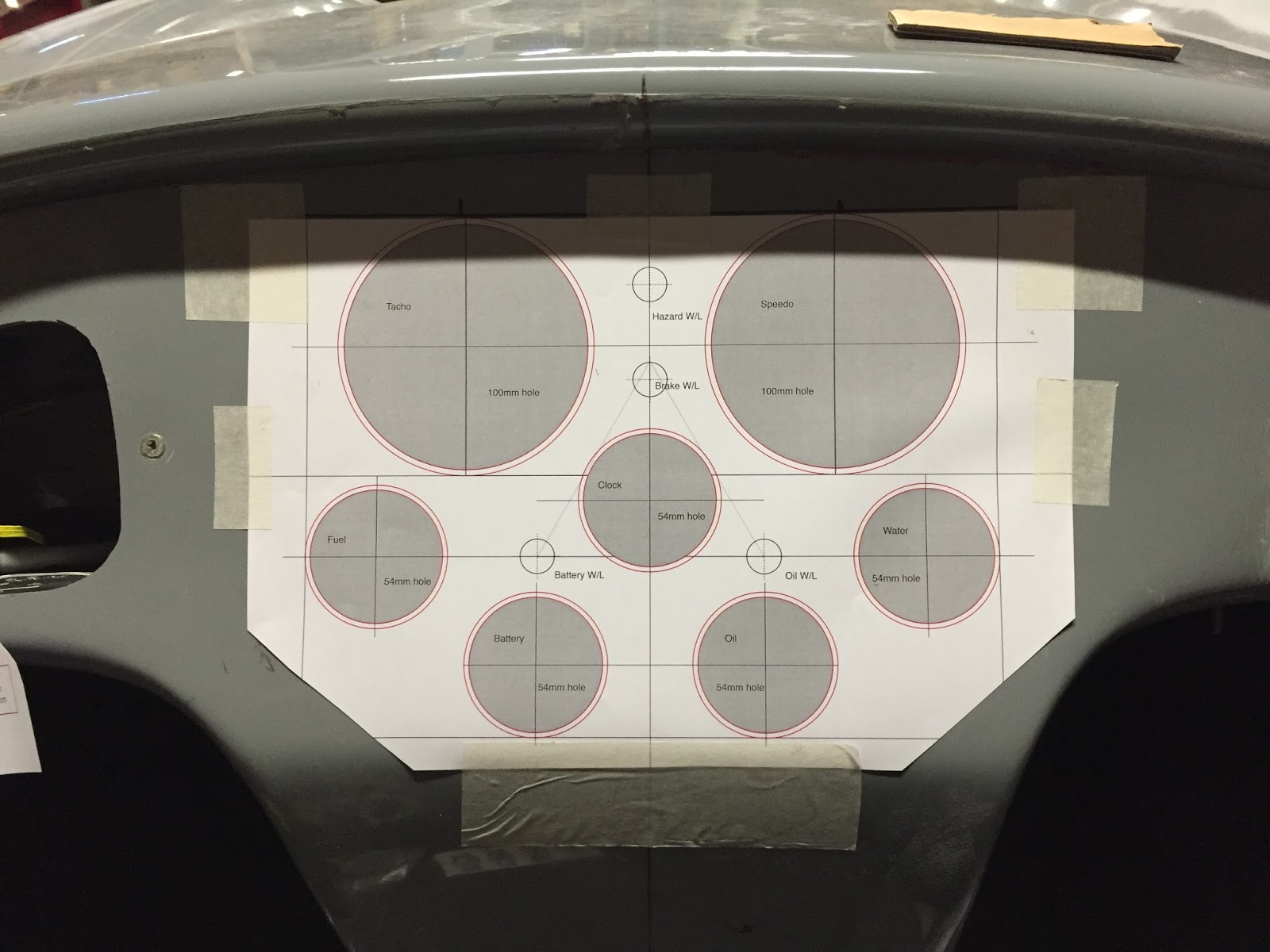
This is the end result! I printed it out on A3 paper, and the circles are all the exact size of my dials, plus an extra 1mm for when the dash is trimmed.
What I really wanted to go for here was the symmetry given by the top 3 smaller dials mimicking the curve of the body lip. I have also dotted some warning lights around the dials (Battery/charge light above the Volt meter, Oil light above the Oil pressure meter and the hazard and brake test light between the two large dials.


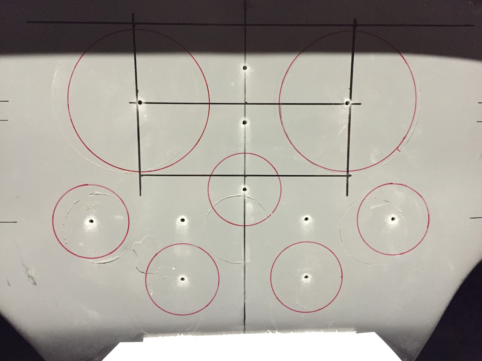
The next part of the puzzle was to transfer the information from this paper to the actually dashboard. I did this by drilling through all the hole centres, as you can here


Once I removed the paper template, you can see that all of the holes line up nicely with my original centre line measurements


I originally bought myself a mathematics compass for drawing circles, but quickly found that the hole to clamp the pen was too small for my permanent markers, so I had to come up with another plan.
I Googled for advice on how to draw circles to specific sizes, and came across a video on how to make a DIY beam compass. So that is exactly what I did. I found a suitable piece of wood (it only had to be quite small) and stuck a screw in one side to act as the pivot and drilled a hole through the other end at exactly 27mm and 50mm (the hole diameters for the Speedhut gauges I have are 54mm and 100mm - with the extra 1mm all round (2mm total) for the dash trim).
I must say that this worked extremely well and I quickly drew all of the circles I needed.


First circle done


Closely followed by all of the others.

This then gave me the outer limits that I need to open the holes up to.


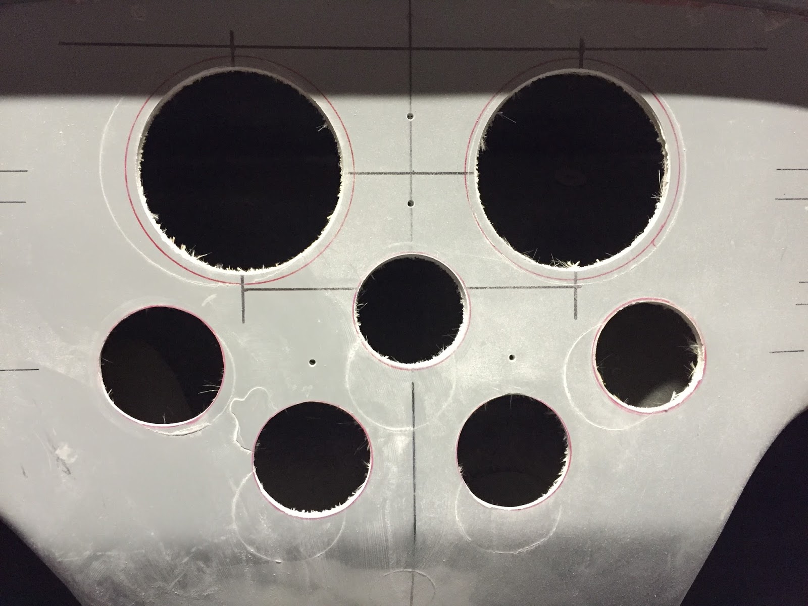
I used a 51mm (2 inch) hole saw for the smaller dials and a 89mm (3.5 inch) hole saw for the larger dials. The warning lights will just be a 14mm hole which I have a 14mm drill bit for.

With the hole saw, I didn't want to cut too close to the edge, so I would have to fine tune by hand. I say by hand, but what this really means is by Dremel!


The Dremel made short work of taking out the remaining fibreglass and I managed to get the holes opened up really easily.

I had to take care not to take too much out as it does disappear quite quickly in to a fine white powder that gets everywhere!

A dust mask is definitely required for this job.


Overall I am really happy with the result.

The next task is to trial fit the dials and drill the holes for the warning lights and toggle switches.

Thursday 25 August 2016

Steering column - Upper section

I needed to fit the steering column in order to ascertain what size hole I needed to cut out for the dashboard. I wanted to do this before I cut the holes for the gauges in the dashboard to make sure that I got the gauges in a sensible place and they would not be obscured by the steering wheel.


The first task was to cut back the metal shroud that sits on the upper side of the column. I mounted the column roughly in place (you can't get it in properly because the part you need to remove is in the way!)
I marked a line where it hit the scuttle hoop and then took the angle grinder to it......


Before......


This is what it looked like after surgery.....


I had to tweak the brackets slightly as the column did not appear to be sitting quite straight, but only a very tiny amount.


And that's it.....column mounted for now.

I have bought two lengths of 8mm threaded bar so that I can use the trick of being able to easily move the column up and down once the dash is in place without having to hold it. I only needed 2 x 20cm lengths as this was enough to drop the column out of the way of the dash.

Door cards


This is another job that I was trying to get done so that I could take them, along with the dashboard, to AK to be trimmed.

I am a little apprehensive about this job, because it seems to all be a little bit of guess work to make sure the door cards are the right size once trimmed and all the door seals on, as I have no idea what the final thickness will be!

However, all I can do is go with what seems to be right, and if it needs fixing later I will deal with it then.


I decided that I would make some templates out of cardboard, so I offered up a piece (I found out that it needs to be at least 70cm long as the first one I cut was not!).....


....and drew around the door edge on the rear of the cardboard with a red maker pen.


This left me with a nice line to cut along to get the initial template.


I did this both sides and cut out the templates. I was not too worried about them being slightly larger than needed. In fact, this was the preferred option as it was hard to get a clean line with the cardboard, but I knew that I got trim the plywood down to suit once that was the rough size needed.


I then transferred the shape to the plywood......


 ....and cut the plywood out with a jigsaw. Remember to label them up with  side they belong to!


 I then stuck the plywood cutouts back to the door and drew around the back again with the red pen. I stuck the top of the plywood to the door with some gaffer tape to stop it from moving.


This then left me with a line to work to to get a better fit with the plywood. I used the jigsaw again to get closer to the red line, and then filed it down by hand from that point.


This left me with a nice looking pair of door cards that have a nice smooth edge to them.


Thursday 11 August 2016

Fuel fillers

Another task that I could tackle without having the body fully bolted down was to mount the fuel fillers.


I started by using a trick that I had seen on the Cobra Club forum, of using a straight edge to draw lines across the recess to find the centre


The lines do not match exactly, but I was expecting that because the recess is not perfectly circular


However, when I then put the fuel filler flange directly over the centre, it did not look right, so I decided this was another job like finding the centreline, and did it by eye!


I centred the filler flange and drew around the base. I then drilled a hole directly through the centre.


Using a 72mm hole saw, I then cut the hole out (I was a bit nervous about this!)


But, I was very happy with the result!


I then repeated for the other side (not sure why I decided on the expensive option of having two fuel fillers!).

Even if I say so myself, it looks pretty good.


The next job here is to drill the holes in the filler flange neck and drill the holes in the body to suit. I have purchased some nice stainless steel, raised head, countersunk, slotted screws for this!

Dashboard......finding the centreline

To continue the story of fitting the dashboard, this is the view after fitting it for the first time


My basic rule of thumb was to try and get the edges as equally close to the edge of the shell as possible, whilst maintaining equal spacing on the centre tunnel.

The next task was to try and find the centreline of the car, so I could transfer this to the dashboard. This in turn would allow me to measure out properly for the gauges.

I had read various posts on the Cobra Club forum about the cars not being symmetrical, and that the best option was to ignore what "proper" measurements tell you and make sure it looks right to the eye.


My method was to run a line (I used an old roll of electrical wire that I had left over from my last build) through the centre of the nose vents.........


......and then measured between the two roll hoop inner legs and made a mark........


.......then laid down the line to go between the two. I then marked where the line went through to top of the front cockpit lip and transferred that down to the dashboard


True to the advice on the forum, when you actually measure where the centreline sits on the dash, it is not central, but it looks right......so that is good enough for me!

The next job is to remove the dashboard, mount the steering column and then figure out what to cut out of the dashboard for the steering column. After that, it will be time to measure and cut holes for the gauges.

Dashboard fitted

This feels like a mini milestone as it definitely makes the car look more like a car!

It's a small thing, I know, but it was quite satisfying to get it fitted. I did have to elongate the holes sideways slightly to get the dash to be central, but it fits in there so tightly that I don't think it will move once the nuts on the back are all tightened up. 

Now I just need to find the centreline!


Friday 5 August 2016

Dashboard (part 1)

The first step to fitting the dashboard was to try to figure out where to drill the mounting holes. The first method was to use some red nail varnish on the end of the bolts that are bonded in to the dash and press it up against the mounting lip.

This had mixed results as you have to push it in quite hard to get it to bend to the curve.

Next option was to make a template out of cardboard to get the correct curvature, and then offer that up against the dash:


We put the cardboard up against the body and drew a line in red marker along it and cut it down to size


We then trimmed the top down until it fitted neatly under the body lip


We then drew a line from the underside of the dash which resulted in us having a perfect template of the width of the lip that needed drilling


We then placed that against the dashboard and marked where the bolts were. We made a small hole and then put this back against the mounting lip and marked through the holes to get the exact location of the holes.

When drilling the holes, we started with a M6 drill bit (the same size as the bolts), but soon realised that the holes would need to be bigger to account for the curvature when the dash is pushed in.

Therefore, we moved to M8 drill bit with an added bit of wiggle and elongation in the holes. We kept opening the holes out slowly and refitting the dash until it was a nice snug fit, but could be put in place and removed fairly easily.

Hibernation Over......

Well.......that two years off went pretty quickly!

Life seems to have a habit of getting in the way of Cobra building sometimes. Some of that is in a good way, in that I got married last year, so that took some focus away from the build, but equally some in a bad way in that I ended up in hospital for 10 days....now diagnosed with Ulcerative Colitis.

But, life goes on and I am now back at full speed with the build, hoping to get it done early next year.

I sold my motorbike and managed to purchase just about all of the parts I need to finish the job, so it is just some time and effort now needed to get it all finished.

Part of that means picking up on this build diary, so here we go........